Blog
Non-planar slicing and firmware.
Every FDM print starts with a slicing decision: where the layers go. Non-planar slicing places layers on curved surfaces, plans collision-free motion for a tilting bed and leans on custom Klipper firmware to execute it.
Scroll to read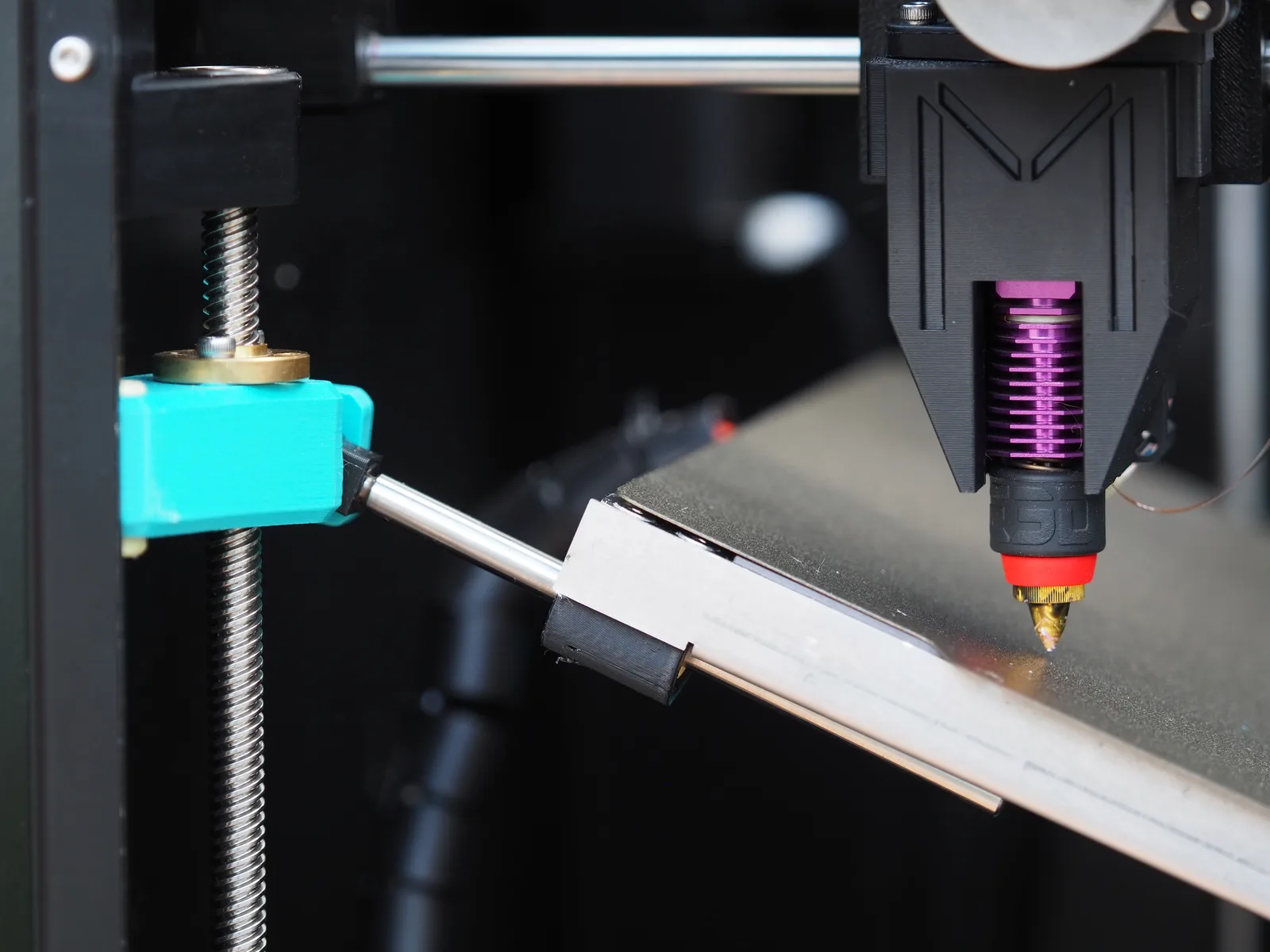
Why can't a standard slicer cut curved layers?
A standard slicer assumes layers are horizontal planes: it intersects the model with parallel planes at a fixed height and emits one flat toolpath per plane. Curved layers break that assumption, so the whole toolchain, slicer, motion planner and firmware, has to change with them.
The planar pipeline is short: load the mesh, intersect it with planes, generate perimeters and infill per slice, emit G0 and G1 moves with a Z step between layers. Every instruction lives in a 2D plane. The toolpath has no way to say that a layer bends, and the machine is never asked to make one bend.
Slicing for a non-planar machine replaces the planes with surfaces. A dome is cut into nested arcs, an arch into concentric bands, an angled wall into layers tilted with the wall. The toolpath becomes fully three-dimensional: within a single layer, Z and bed tilt change continuously.
That is also why the firmware changes. The MK1's bed rides on three lead screws, giving it three degrees of freedom: height plus tilt about two axes. Stock motion firmware has no kinematics for that, so the machine runs a custom Klipper build, and the slicer ships on the downloads page.
Inside a non-planar toolchain
Each stage of the standard pipeline grows an extra dimension: the slicing surfaces curve, the toolpaths move in 3D, collision checking becomes mandatory, and the firmware mixes more actuators into every single move.
- Slicing surface
- Stock: parallel planes. Non-planar: curved surfaces that follow the part
- Toolpath
- Stock: flat loops, one Z per layer. Non-planar: 3D paths where Z and tilt change continuously
- Collision check
- Stock: rarely needed, the nozzle sits above flat layers. Non-planar: every path simulated against the printed part and the tilted bed
- Kinematics
- Stock: Cartesian X, Y, Z. Non-planar: X, Y, Z plus a bed with height and two tilt axes
- Firmware
- Stock: stock Marlin or Klipper. Non-planar: custom Klipper coordinating all actuators per move
- Prep time
- Stock: slicing is near-instant. Non-planar: slicing adds collision simulation
Collision checking is the stage planar users never think about. On flat layers the nozzle body always sits above printed material; only the tip touches the current layer. On curved paths the nozzle sweeps at an angle through space the part may already occupy, so the slicer verifies every move against a model of the growing part. The MK1's narrow, extended nozzle exists for the same reason: a conventional square heat block collides at angles a linear one still clears.
There are hard limits, and the software respects them rather than hiding them. Layers can only tilt as far as the nozzle can reach without a collision, which is why a horizontal ceiling still needs support. The limits are design constraints rather than slicer bugs: designing parts for non-planar printing covers working within them, and the hardware behind them is on the product page.
Frequently asked questions
Can Cura or PrusaSlicer slice non-planar models?
Not for a tilting-bed machine. Stock slicers cut flat layers and nothing else, and experimental non-planar forks exist for research use only. Full curved-layer slicing with collision checking takes a dedicated non-planar slicer, like the one built for the Melta MK1.
What is different about non-planar G-code?
Every move coordinates more axes. Instead of one Z height per layer, toolpaths change height and bed tilt continuously, so the nozzle follows the curved layer while staying clear of the printed part.
Why does non-planar printing need custom firmware?
Because the motion system has more actuators to mix: three lead screws give the bed its height and two tilt axes. Stock firmware has no kinematics for that, so the MK1 runs a custom Klipper build coordinating all of them in every move.
How does the slicer avoid nozzle collisions?
By simulating the toolpath against the part before printing. On curved paths the nozzle body, not just the tip, sweeps through the build volume, so every move is checked against the already printed material and the tilted bed.
What are the limits of non-planar slicing?
Layers can only curve and tilt as far as the nozzle can reach without a collision. Surfaces past the machine's tilt range, true internal ceilings and some deep cavities still need supports or a different design.
Is the Melta MK1 slicer available?
Yes, from the Melt3D downloads page, together with firmware and documentation. It is built for the MK1's tilting bed and generates the curved, collision-checked toolpaths described here.
See the toolchain.
The Melta MK1 ships with its own non-planar slicer and custom Klipper firmware, built for the tilting bed.
Get in touch
Questions about the Melta MK1, the reservation or a possible partnership? Write or call us.