Blog
Designing for non-planar printing.
Non-planar printing rewards geometry planned for it. Orient shells so the layers carry the load, keep surfaces inside the 45-degree tilt range, and design parts that never meet a support.
Scroll to read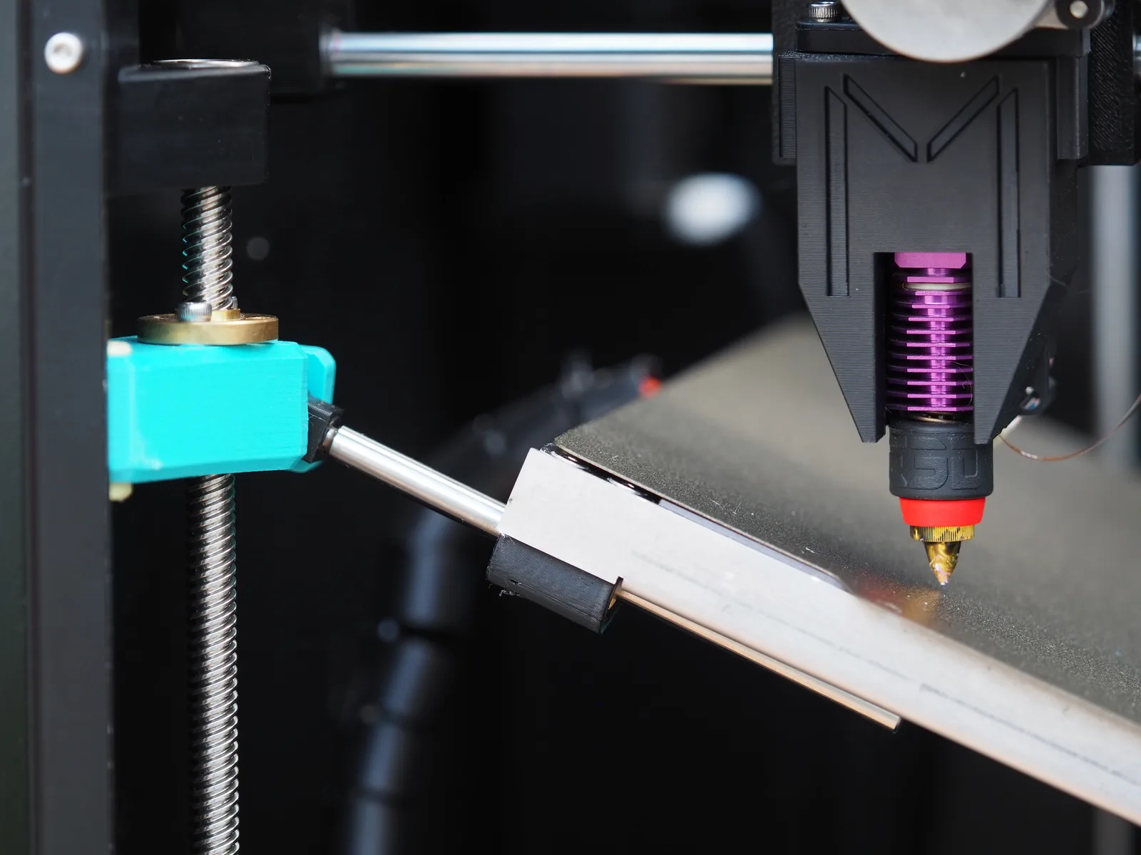
What does non-planar change about design?
It turns the layer plane from a fixed fact into a design variable. On a planar machine every part is a stack of horizontal cuts, so you design around steps, supports and one weak plane; on a non-planar machine the layers can follow your surfaces, so the geometry you draw is much closer to the geometry you get.
Curved shells print smooth and strong, because layers run along the surface instead of across it, and overhangs within the 45-degree tilt range print without supports. The surfaces you model are the surfaces you keep: no support scars to sand, no stack of interfaces where a bracket wants to crack.
What does not change is the material. It is still 1.75 mm FDM filament, so wall thickness, minimum features, hole clearances and tolerances behave the way they always have. Non-planar printing changes where the layers go, not how plastic behaves.
One thing to plan around: the build volume tilts. The bed measures 235 × 220 mm and rotates up to 45°, so a long shallow arch may fit diagonally where it would not fit upright. Thinking in the tilted frame early saves re-orientation later; the hardware limits are detailed on the product page.
Six rules for non-planar parts
Orient curves along the load
Layers are strongest along their length, so let them run parallel to the force. A bracket printed with layers following the shell is loaded in the strong direction; printed flat, it is a stack of peeling interfaces. The mechanics are covered in curved-layer strength.
Stay inside 45 degrees
Check every overhung surface against vertical in CAD. Within the bed's 45-degree tilt range it prints from the side, support-free; past it, nothing has changed from planar printing. Rotate the part in CAD, not after a failed print. The details are in overhangs without supports.
Model curves, not steps
Model the true curve. There is no need to approximate a dome with chamfer stacks or flatten an arc to appease the process: the slicer follows the surface, and the part comes out as drawn.
Design them out
Support scars used to decide which faces were presentable and which were sacrificial. Inside the tilt range that constraint is gone: put appearance surfaces, sealing faces and threaded holes under overhangs, because nothing will touch them.
Think in the tilted frame
The part rotates as it prints, so clearance is not a simple box. Long shallow arches fit diagonally; tall parts may need to lie down. A ten-minute orientation study in CAD beats a failed twelve-hour print.
Know when planar is enough
Boxes, plates and straight-walled enclosures already fit flat layers, and printing them non-planar adds motion without adding anything to the part. The trade-offs are laid out in non-planar vs planar.
Frequently asked questions
How should I orient a part for non-planar printing?
Put the layer paths where the loads flow. Curved shells should print with layers following the shell, so forces pull along layers instead of peeling interfaces apart, and overhung surfaces should stay within 45 degrees of vertical so the bed can tilt into them.
What geometry benefits most from non-planar printing?
Domes, arches, spheres, curved brackets and angled walls: parts whose surfaces slope or curve. Prismatic parts with straight vertical walls gain little, because flat layers already fit them.
Do I still need supports when designing for non-planar printing?
Far fewer. If every overhung surface stays within the bed's 45-degree tilt range, the part prints support-free. True horizontal ceilings and narrow internal channels beyond that range still need supports or a redesign.
Can I print existing CAD models non-planar?
Yes, the same STL or STEP files work. What changes is how you orient them: features that planar printing forced you to split or thicken can often print as designed once layers can follow the surfaces.
Does non-planar printing change tolerances?
No. Wall thickness, minimum features and hole clearances behave like standard FDM in the same material. Curved surfaces actually hold their shape better, because layers follow the surface instead of stepping across it.
How big can a non-planar part be?
Within the machine's tilted build volume. The Melta MK1's tilting bed measures 235 x 220 mm and rotates up to 45 degrees, so parts are planned inside that tilting envelope rather than a simple box.
Design for it.
Model the curve, orient the load, skip the supports. The Melta MK1 prints what CAD intended.
Get in touch
Questions about the Melta MK1, the reservation or a possible partnership? Write or call us.